Project
ABB Lifter Force Analysis Study
Two industrial scissor lifts, taken from geometry to load path to a punch list of fixes.
A statics study of two industrial scissor lifts analyzed during my robotics internship, checking each against a 1000 kg payload target across its real travel envelope and stating what it needs to carry that load safely. Full derivations and calculation source are in the two subpages; this page is the summary of both machines.
The numbers were independently re-derived by three verification passes, two adversarial (one for statics and geometry, one for materials and failure theory) and a third that rebuilt the closed form from scratch and checked all 68 published quantities, and reviewed by K. All 68 reproduce within rounding. The third pass also found three modeling omissions on the arm sections, corrected on these pages. The validation covers the arithmetic and statics.
Shaft lifter
Objective: the machine is in service development. Determine whether its structure can carry a 1000 kg payload (plus a roughly 150 kg platform, safety factor 1.5 on working weight) throughout its real travel envelope, and what must be corrected for it to do so safely. Actuation sizing is excluded from scope and remains the vendor's responsibility; the structure's force demand is stated where the vendor needs it. Actuation-side components, including the cylinder cross member, are the actuation vendor's scope and were not analyzed.
Measured basis
All dimensions were taken from the supplied CAD assembly through section cuts and dimension callouts.
Geometry
- Arm pin-to-pin 1565 mm; half-arms 782.50 / 782.50 mm (the arms cross at their midpoints).
- Working pose: horizontal pin span 1542.05 mm, vertical pin spacing 267.0 mm, arm angle 9.82 degrees. The three values form a self-consistent triangle and check against each other.
Travel
- Piston travel 167 mm total, 120 mm usable.
- The modeled pose is the working position, not the bottom: the piston travels 19.92 mm below it (to the true closed position at 3.56 degrees, piston bottomed, pins at 97 mm) and 100.08 mm above it (to the top at 22.9 degrees, pins at 608 mm).
- Platform range: 170 mm below the working pose, 341 mm above, 511 mm total.
Joints and members
- Arm-end hinges, outside to inside: block, arm plate, roller, arm plate, block (double shear). The bores step 18 mm (blocks) / 24.1 mm (arm plates) / 31 mm (roller). No axle exists in the model; analysis proceeds on an 18 mm plain pin, the diameter the block holes govern.
- Center pins: 24 mm diameter with 29 mm rivet heads in 24 mm holes, double shear, fully fitted.
- Arms: two flat bars per arm, 6 mm thick each, measured at 25 mm depth at the crossing.
- Sliding ends: two linear bearing blocks per end, top and bottom.
- Material assumed mild steel (yield 250 MPa, shear yield 145 MPa); the grade could not be confirmed.
Note: the vault report embeds raw CAD captures of the side profile, the piston section, and the hinge stack here. Those are omitted to avoid CAD-borne part identifiers; the governing geometry and the joint stack are reproduced in the derived diagrams below.
The mechanics
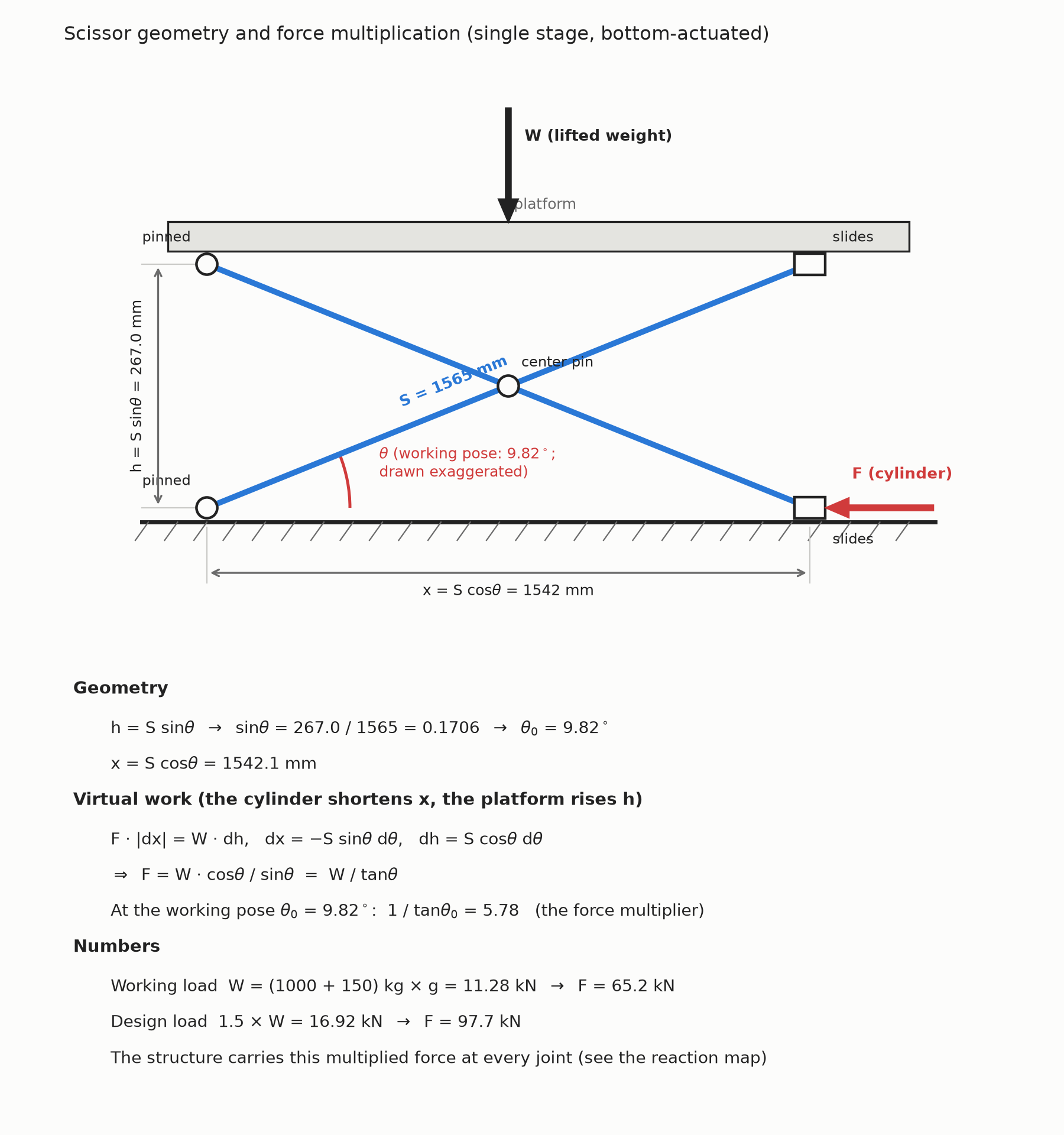
Geometry and force multiplication: the horizontal force is the lifted weight divided by the tangent of the arm angle, 5.78x at the working pose.
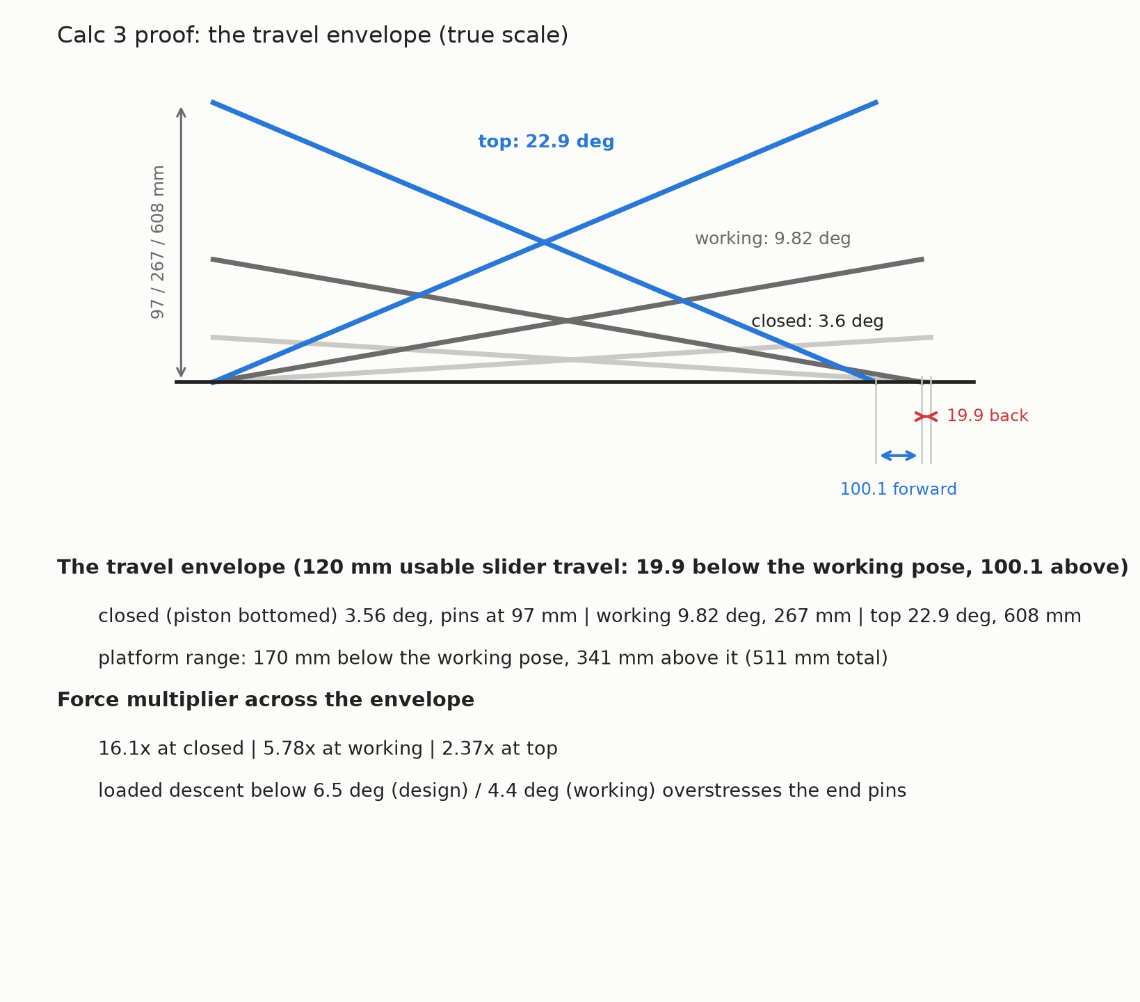
The travel envelope at true scale. The multiplier swings from 16.1x at closed, through 5.78x at working, to 2.37x at top.
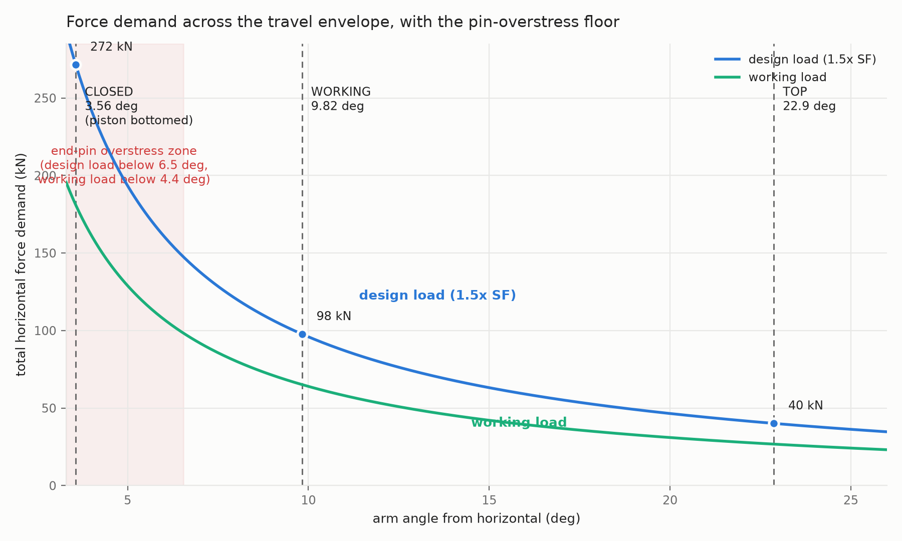
Force demand across the envelope. The shaded band is where the end pins exceed allowable stress; the closed position sits inside it.
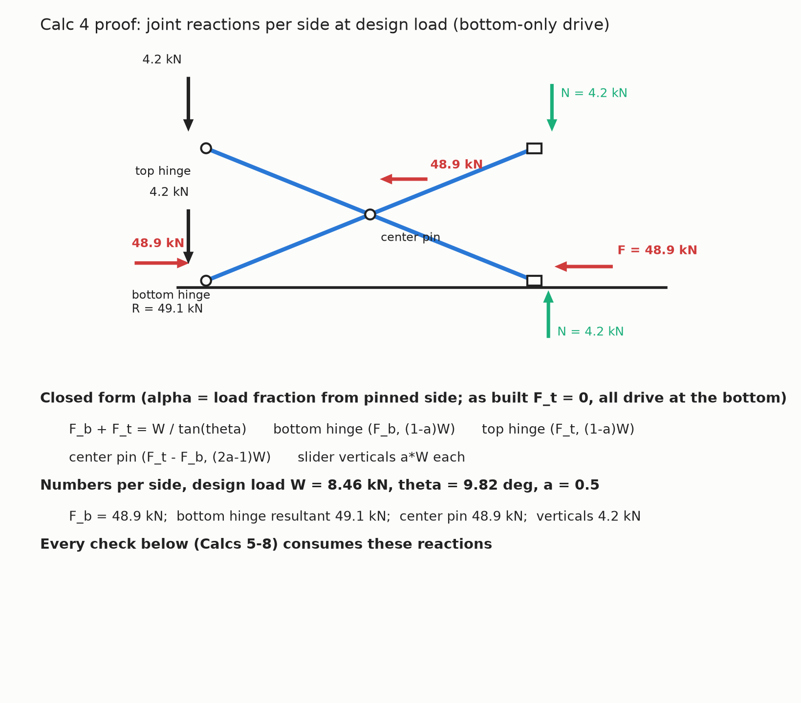
The joint reaction map at the working pose, design load: end hinges 49.1 kN per side, center pins 48.9 kN, slider verticals 4.2 kN. The top hinges carry no horizontal force; every structural check consumes these reactions.
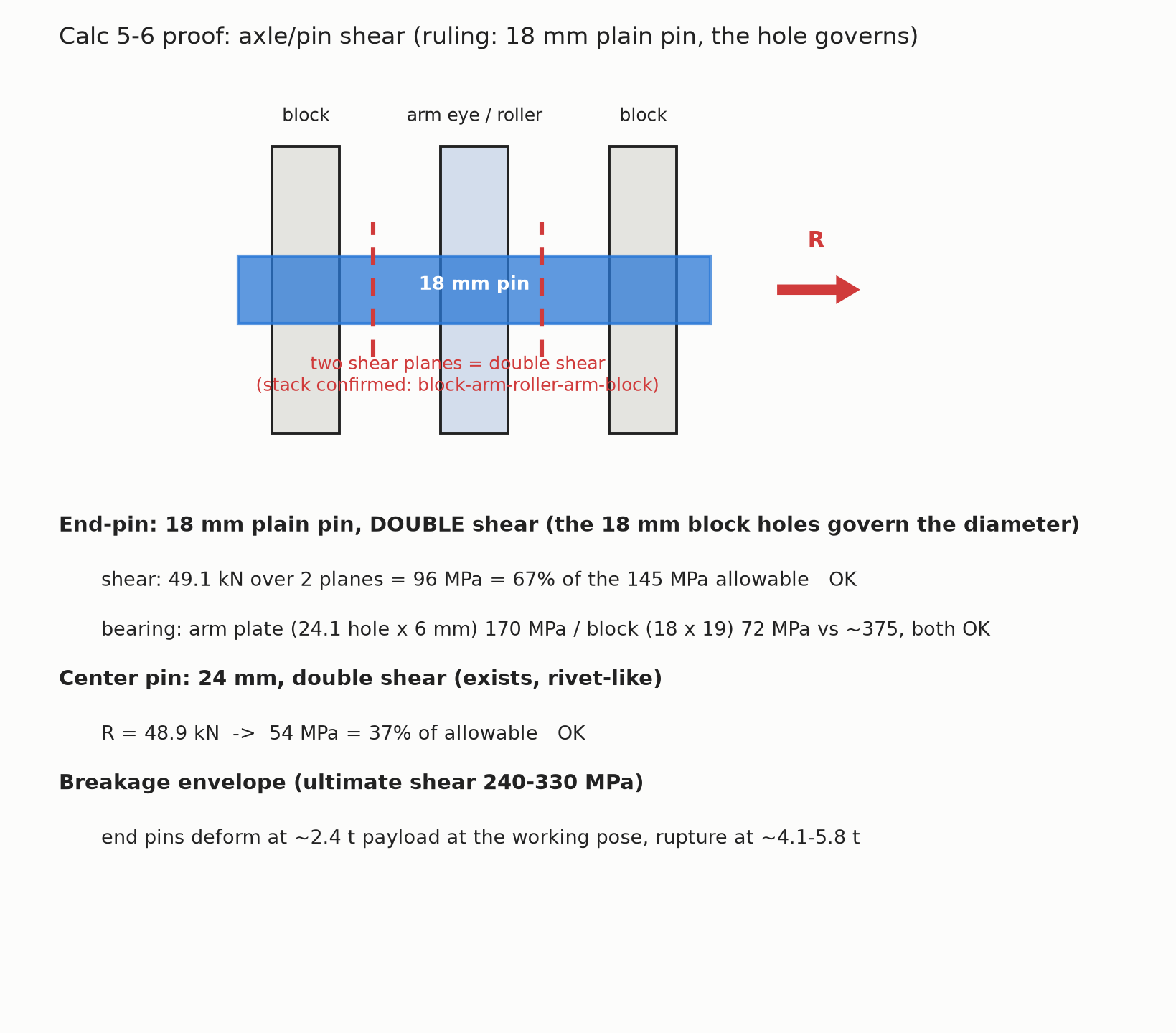
Pin shear at the working pose: the 18 mm end-pin in its confirmed double-shear stack runs 96 MPa (67% of allowable); the 24 mm center pin 54 MPa (37%). Bearing stresses pass. End pins deform permanently at roughly 2.4 tonnes of payload at the working pose, rupture at 4.1 to 5.8 tonnes.
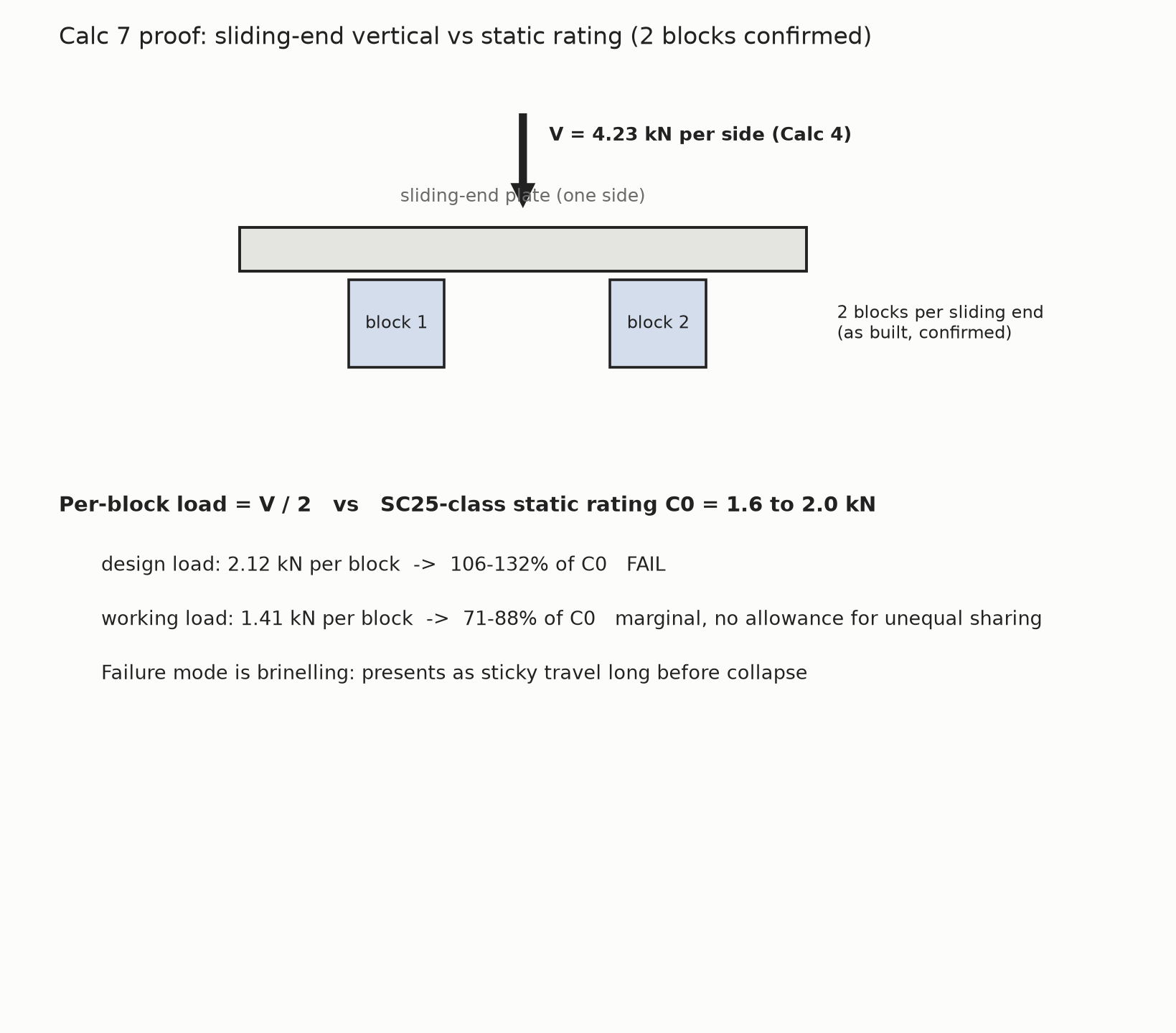
Sliding-end linear bearings: 2.12 kN per block at design load is 106 to 132 percent of the static rating, at any angle. This is the machine's first structural failure under full load.
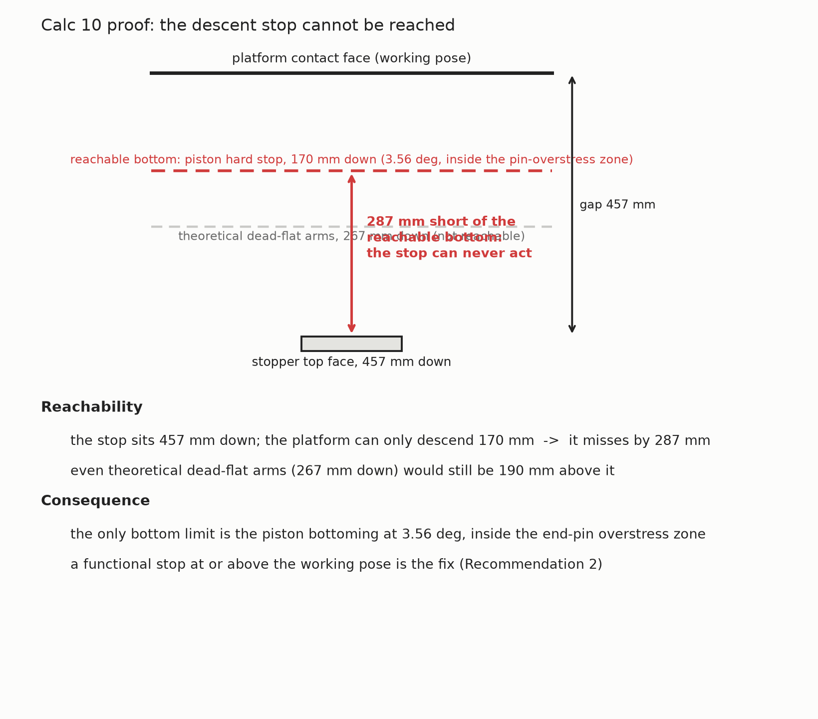
The descent stopper: its top face sits 457 mm below the platform against 170 mm of reachable travel, so it misses by 287 mm and can never engage. The only bottom limit is the piston bottoming at 3.56 degrees, inside the pin-overstress zone.
Results
- Joints at the working pose: adequate. With a proper 18 mm double-shear pin at each arm-end hinge, all pin shear and bearing stresses pass with margin (end pins 67 percent, center pins 37 percent, bearing under half of allowable). But the axle is a stepped or sleeved custom pin that was never drawn, specified, or retained, so the hinge is unbuildable as documented even though its stresses check out.
- The travel envelope is the risk map. Loaded descent below 6.5 degrees (design load) or 4.4 degrees (working load) overstresses the end pins, and the true closed position, 3.56 degrees, is inside that zone. With 1000 kg aboard at the bottom the outcome is permanent pin deformation, not rupture. An empty platform may be parked at closed without harm.
- Capacity is pin-governed: 474 kg rated payload at the 1.5 safety factor from the lowest point (3.56 degrees, 16.1x), or 786 kg loaded to the shear allowable with no safety factor. The 1000 kg rating exists only at or above the working pose, and remains contingent on closing the open items below.
- Sliding-end linear bearings fail at design load (106 to 132 percent of static rating), independent of angle. Expected mode is brinelling, presenting as sticky travel well before collapse. The rating is a class assumption: an LM25-class carriage at 1.37 kN would put the blocks at 154 percent, so confirm the fitted part number.
- All fasteners on the primary load paths are unmodeled (hinge hold-downs, cylinder bracket); roughly 49 kN per hinge must pass through bolts that exist only as cosmetic features.
- The descent stopper is non-functional (287 mm short of the reachable bottom), leaving the pin-overstress zone unguarded.
- The arm section is unresolved, and it is an open input rather than a broken model. An earlier reading treated the bending idealization as suspect, because a 25 mm depth returns roughly ten times yield while the machine demonstrably stands. An independent re-derivation settles it the other way: the bending model is right and the 25 mm figure cannot be the depth, since a 24.1 mm hole through a 25 mm deep plate leaves 0.9 mm of material. Nor are these arms two-force members; the free body gives a genuine 3.26 kN.m moment at the crossing, peaking at the pin hole, alongside 48.9 kN of axial compression at the same section. Including both, a 2 by 6 mm plate pair needs roughly 100 mm of depth to stay inside yield at design load. The depth has never been measured, and the capacity claim is contingent on it.
Open items (punch list)
- Fit a third linear bearing block per sliding end, or higher-rated carriages. This removes the one outright structural failure at design load.
- Install a functional descent stop that engages at or above the working pose, so a loaded platform can never be driven into the low-angle overstress zone. This is a prerequisite for any actuation upgrade.
- Specify and positively retain the arm-end axles, stepped or sleeved to match the stepped bores.
- Measure the arm plate depth at the crossing and close the beam-column check. Roughly 100 mm is needed in 2 by 6 mm plates to clear design load with axial included.
- Confirm the sliding-end carriage part number and its true static rating before sizing the bearing fix.
- Specify the hold-down and bracket bolts on the primary load paths.
- Confirm material certificates before build.
For the actuation vendor: the structure demands 97.7 kN total at the working pose (65.2 kN at working load), falling with height along the demand curve above.
Why the top hinge carries no horizontal force
It is the question every engineer asks first when they see one hinge design used top and bottom. Treat the platform as a free body. Its only horizontal connections are the top hinge and the top roller, and a frictionless roller transmits no horizontal force, so horizontal equilibrium of the platform forces the top hinge's horizontal reaction to zero. The entire multiplied actuation force (93.6 kN per side on the case lifter, 48.9 kN per side on the shaft lifter) stays in the bottom half of the machine and circulates between the arms, the base pins, and the cylinder. The top hinge only carries its small vertical share. Real rollers are not perfectly frictionless, so roller friction adds an estimated 10 to 20 percent, which is why the top hinge is small rather than exactly zero.
Case lifter
Verdict: every joint passes across the entire travel envelope, and the arms reach nominal yield at the holed section under design load. Real 25 mm double-shear axles with retention (95 MPa, 66 percent), a 30 mm center bushing (46 to 91 percent), ball-bearing rollers at 38 percent of rating, a solid pusher block, and a modeled 5.23 degree pose that is genuinely the bottom of stroke, so no hidden low-angle trap exists. The bent-bar failure mode of a thinner design has been engineered out. For the actuation vendor: the 10.92x multiplier at the 5.23 degree floor demands 187.1 kN total at design load.
Arm correction. The solid 25 by 70 mm arms were first published at 169 MPa, 68 percent of yield. That figure counted bending only. The same section also carries 93.6 kN of axial compression, and the peak moment sits exactly at the 30 mm pivot hole where the net area drops to 1000 mm2. Combined at that section the arm runs 263 MPa, 105 percent of yield at the 1.5x design load and 70 percent at working load, so the realised safety factor on the arm is about 1.43. Local yielding at a pin hole in ductile steel redistributes rather than fractures, so this is a margin finding and not a failure prediction, but it makes the arm, not the axles, the governing member. Weak-axis buckling passes at 3.5x, and only because the centre pivot braces the arm.
Two open risks remain: the arm margin above, and a behavioral one, two independent cylinders with no synchronization. Racking under uneven extension loads the lagging side's hinge beyond its half share and twists the arms; a flow divider or mechanical tie remains the leading recommendation.
Measured basis
- Arm pin-to-pin 1490.09 mm; half-arms 745.04 / 745.04 mm; working pose span 1483.87 mm, vertical 135.87 mm, angle 5.23 degrees (the true bottom of stroke, confirmed).
- Piston stroke 50 mm; one hydraulic cylinder per scissor side, independent.
- Main hinges: 25 mm axle in double shear with retention. Center pivot: bushing, 30 mm load-bearing diameter.
- Arms: single solid plates, 25 mm thick by 70 mm deep. Sliding end on ball-bearing rollers, no linear slides.
- Lifted structure roughly 164 kg. Material assumed mild steel (yield 250 MPa, shear yield 145 MPa); grade unconfirmed.
Note: the vault report embeds a raw CAD side-profile capture here. It is omitted to avoid CAD-borne part identifiers; the governing geometry is derived in the diagram below.
The mechanics
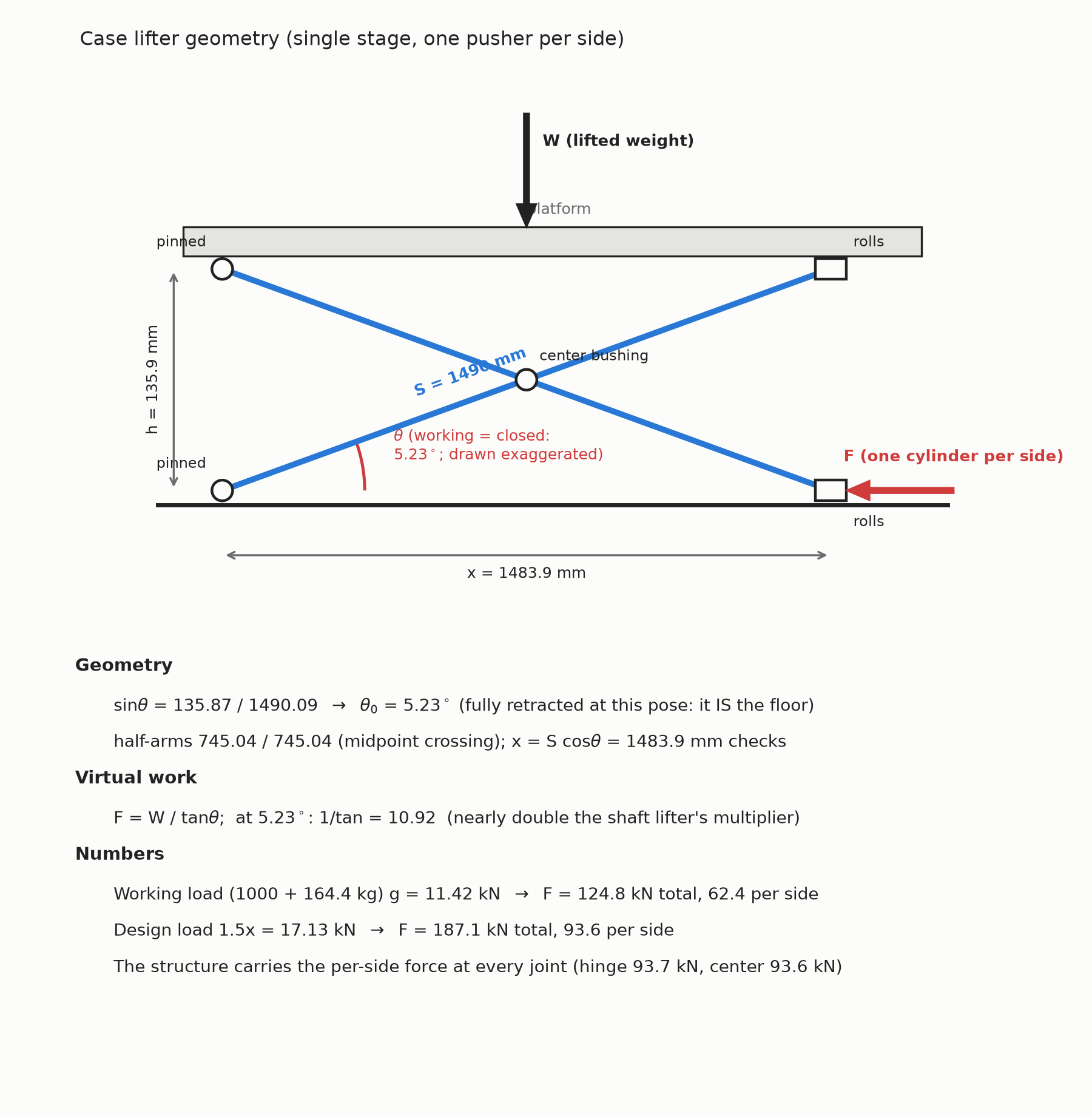
Case lifter geometry and derivation: half-arms 745.04 / 745.04, span 1483.87, vertical 135.87, angle 5.23 degrees, 10.92x multiplier.
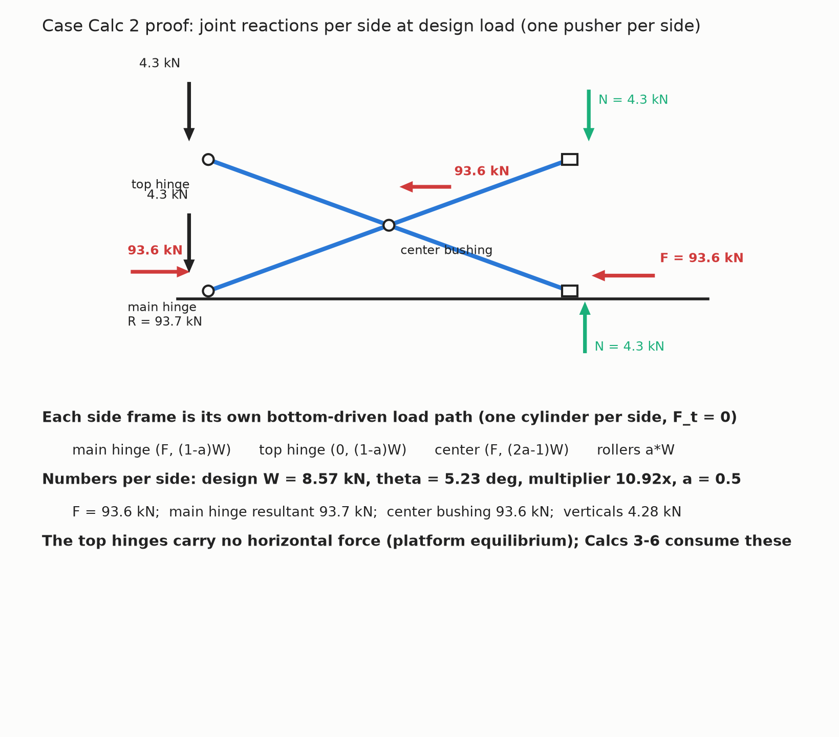
Joint reactions per side at design load: main hinge 93.7 kN, center pivot 93.6 kN, roller verticals 4.28 kN. The top hinges carry no horizontal force.
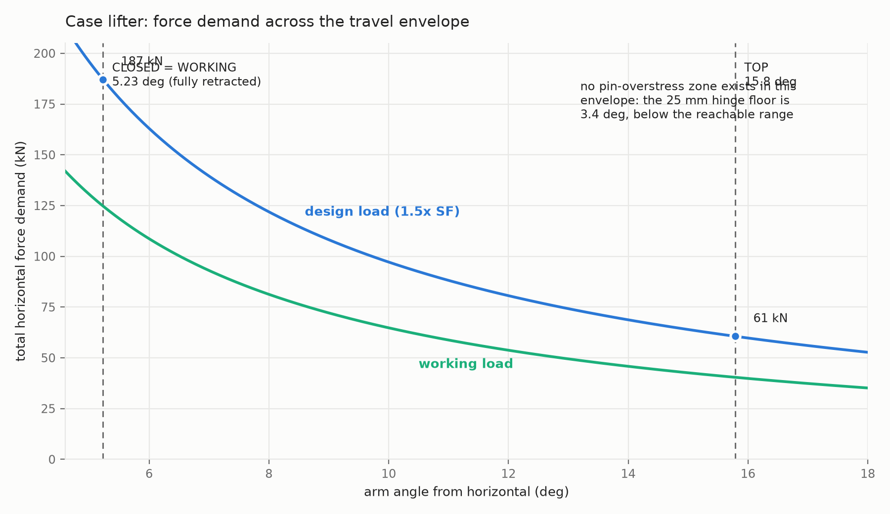
Case lifter force demand across its envelope, from 187.1 kN at the floor to 60.6 kN at the top.
Results and recommendations
- Main hinge axles 66 percent, center pivot 46 percent (double shear) and still inside allowable at 91 percent read as single shear, rollers 38 percent of rating. Every joint passes across the whole 5.23 to 15.8 degree envelope.
- Arms 105 percent of yield at the holed section under design load once axial compression is included, 70 percent at working load. The governing member, at a realised safety factor of about 1.43.
- Add cylinder synchronization: a flow divider, a rephasing circuit, or a mechanical tie between sides. Racking loads the lagging hinge beyond its half share and twists the arms.
- Confirm the centre pivot gives genuine lateral restraint to the arm; the weak-axis buckling check passes only on that assumption.
- Verify the center pivot's double-shear construction next time the joint is opened; the 91 percent single-shear reading is the thinnest joint margin on the machine.
- Confirm material certificates at build.
Assumptions and limitations
- Material grade is unconfirmed; all stresses assume mild steel at a yield of 250 MPa.
- The only safety factor is 1.5 on the working weight, applied to the load. The 145 MPa shear figure is the shear yield, not a further-reduced allowable.
- Static analysis only: no dynamic or impact factor, no fatigue, and no stress concentration at holes.
- Deformation and rupture loads are isolated pin-shear values on assumed steel; other components govern well below them.
- The case lifter's center pivot is checked as steel shear only. The bushing material's own bearing pressure limit was not evaluated (projected pressure roughly 95 to 125 MPa depending on bush width); flagged for follow-up with the bushing specification.
- The lifted mass is payload plus platform. Arm self-weight is excluded, worth roughly 3.5 percent on the case lifter, whose 164 kg platform figure is measured with no padding.
- Frictionless pins and carriages. Real friction adds an estimated 10 to 20 percent to breakaway force and is not included in any figure here.
- Lug edge distance and tear-out were not checked on either machine, because plate edge geometry was never captured. Welds were not assessed. The analysis is 2D throughout, so racking, twist and rail misalignment are outside the model.
- Actuation-side components, including the shaft lifter's cylinder cross member, are the actuation vendor's scope and were not analyzed.
Read the full analysis for each machine: