Case Study
Case Lifter Study
A scissor lift that passes every structural check, with one behavioral risk left to close.
The in-depth structural analysis of the case lifter: real axles, a solid arm section, and a genuine bottom-of-stroke pose, so the whole envelope checks out, leaving cylinder synchronization as the sole open item.
Verdict: every joint passes across the entire travel envelope. The arms are the tightest member and reach nominal yield at the holed section under design load once axial compression is counted. The other open risk is behavioral, not a part: two independent cylinders with no synchronization.
Scope
The same 1000 kg payload target (plus a roughly 164 kg platform, safety factor 1.5 on working weight), the same mild-steel assumption (yield 250 MPa, shear yield 145 MPa), and the same static method as the shaft study. This machine is a single-stage scissor with one hydraulic cylinder per side. Actuation sizing is out of scope; the force demand is stated for the vendor.
Force required to lift
Same mechanics as the shaft lifter, from a worse angle. At 5.23 degrees the multiplier is 10.92x, so the 17.13 kN design load demands 187.1 kN of total horizontal push, or 93.6 kN per side, falling to 60.6 kN total at the 15.8 degree top. Because the modeled pose is the true bottom of stroke, this worst case is the floor, not a hidden low-angle trap.
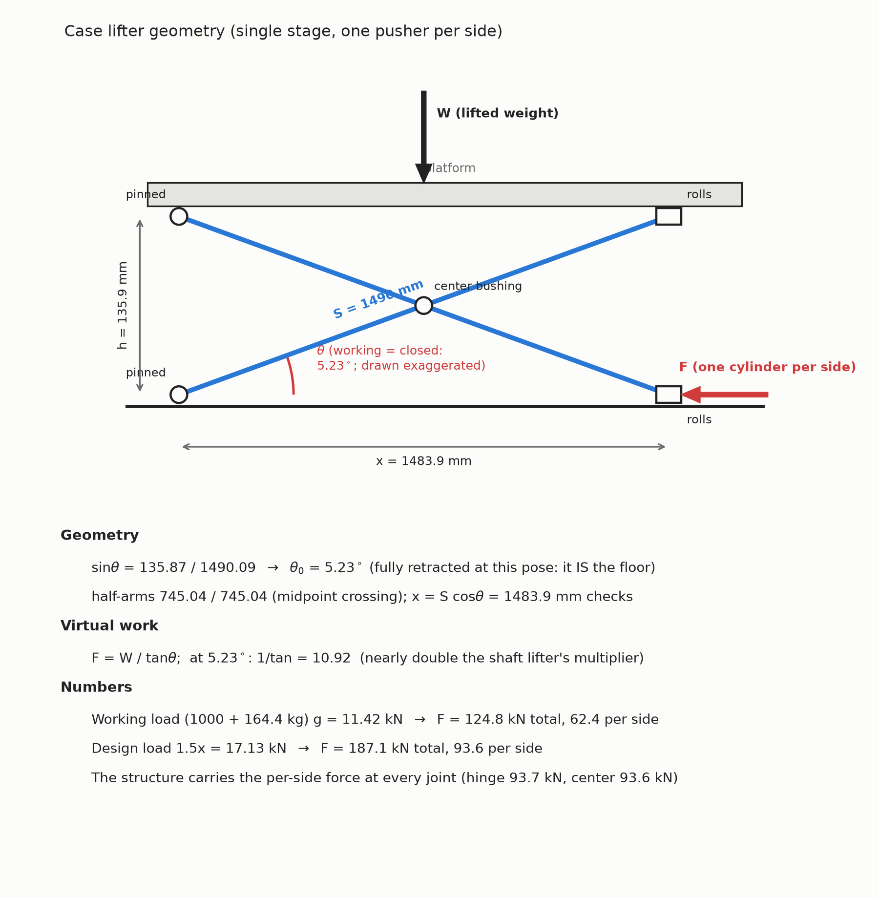
Geometry and derivation at the 5.23 degree floor.
The joint reaction map
With one pusher per side, each side frame is its own bottom-driven load path. At design load the main hinge sees 93.7 kN resultant, the center pivot 93.6 kN, and the roller verticals 4.28 kN per side. As on the shaft lifter, the top hinges carry no horizontal force by platform equilibrium.
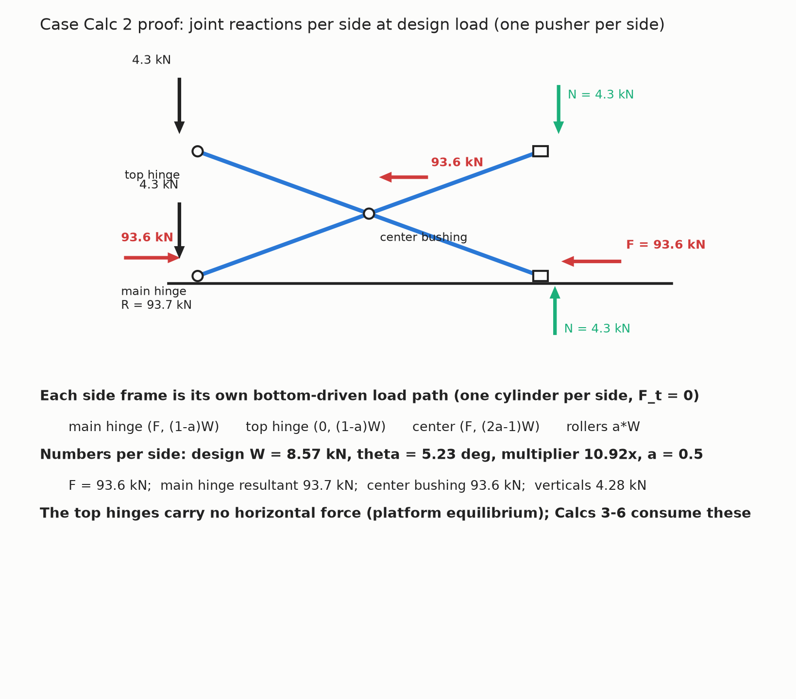
Reactions per side at design load.
Structural checks
| Check | Result | Verdict |
|---|---|---|
| Main hinge axles (25 mm, double shear, with retention) | 95 MPa (66%); overstress floor 3.4 deg, below the reachable range | Pass everywhere in the envelope |
| Center pivot (30 mm load-bearing bushing) | 66 MPa (46%) double shear; 132 MPa (91%) even single shear | Pass |
| Arm section (solid 25 by 70 mm arms, 30 mm hole) | bending alone 169 MPa (68%); bending plus 93.6 kN axial at the holed section 263 MPa, 105% of yield at design load, 70% at working load | Pass at working load, at yield at design load; the governing member |
| Arm weak-axis buckling (braced at the centre pivot) | 53 MPa applied against an Euler stress of 190 MPa, 3.5x margin; 0.9x if the arm were unbraced over its full length | Pass, on the assumption the pivot restrains the arm laterally |
| Rollers (ball-bearing) and pusher block | 4.28 kN per side, 38% of static rating; block strong by inspection | Pass |
| Travel envelope and synchronization | 5.23 to 15.8 deg, modeled pose = full retraction; two independent cylinders | Envelope clean; sync is the open risk |
Axle and bushing shear
The main hinge is a 25 mm axle in double shear, confirmed by section, with retention screw holes. At 93.7 kN it runs 95 MPa, 66 percent of allowable, and its overstress floor of 3.4 degrees sits below anything the 50 mm stroke can reach, so no reachable pose overloads it. On the breakage envelope, the main hinges deform at roughly 2.5 tonnes of payload at the working pose and rupture between about 4.2 and 5.9 tonnes.
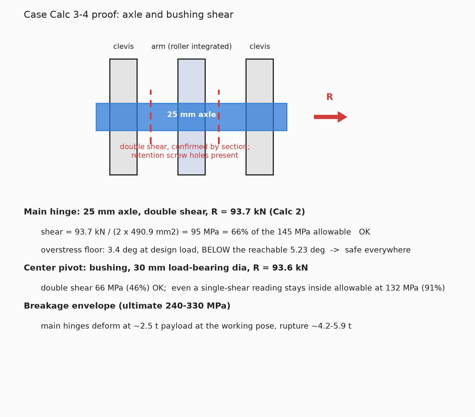
Axle and bushing shear, with the breakage envelope.
The arm section
The arms are solid plates, 25 mm thick and 70 mm deep, with a 30 mm hole at the crossing. The net section modulus against the 3.18 kN.m center moment gives 169 MPa, 68 percent of yield, at the worst pose. That is the bending answer, and it is correct as far as it goes.
It is not the whole answer. The arm is a beam-column, not a beam: the same section also carries 93.6 kN of axial compression, which is the full per-side drive force resolved along the arm, and the peak moment sits exactly at the pivot hole where the net area drops to 1000 mm2. Both peak at the same place. Combined, that section runs 263 MPa, 105 percent of yield at the 1.5x design load and 175 MPa, 70 percent, at working load. The realised safety factor on the arm is about 1.43 rather than 1.5. Local yielding at a pin hole in ductile steel redistributes rather than fractures, so this is a margin finding and not a failure prediction, but it means the arm, not the axles, is what governs this machine.
Weak-axis buckling is the companion check. At 25 mm thick over a 1473 mm length the radius of gyration is 7.2 mm, so the applied 53 MPa sits against an Euler stress of 190 MPa when the arm is braced laterally at the centre pivot, a 3.5x margin, and against 47 MPa if it were unbraced over its full length. The pivot ties each arm to its partner and the frames are tied by the platform, so the braced case is the realistic one. The member passes because of the brace, not because the section is stout.
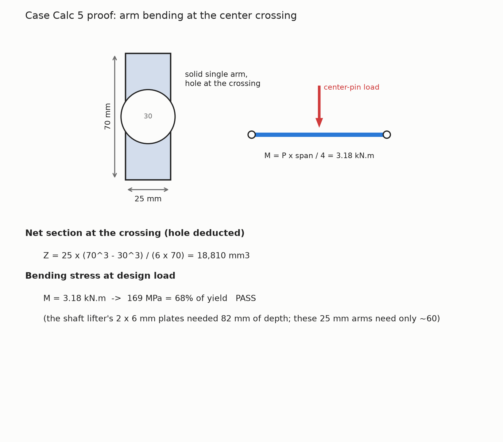
The arm section and the bending check as first published. The axial term above is added on top of this figure.
The travel envelope and the open risk
The modeled pose is full retraction, so the envelope is exactly 5.23 to 15.8 degrees and every joint in it passes. The remaining open structural risk is behavioral: two independent cylinders with no flow divider, sync valve, or mechanical tie. If one side leads, the platform racks, the lagging side's hinge sees more than its half of the load, and the arms take out-of-plane twist that the 2D checks do not cover. At 66 percent axle utilization there is real margin to absorb moderate imbalance, but the arms sit at 105 percent at the holed section under design load and have much less room for an uneven share. Synchronization hardware is cheap and the loads here are 93 kN a side.
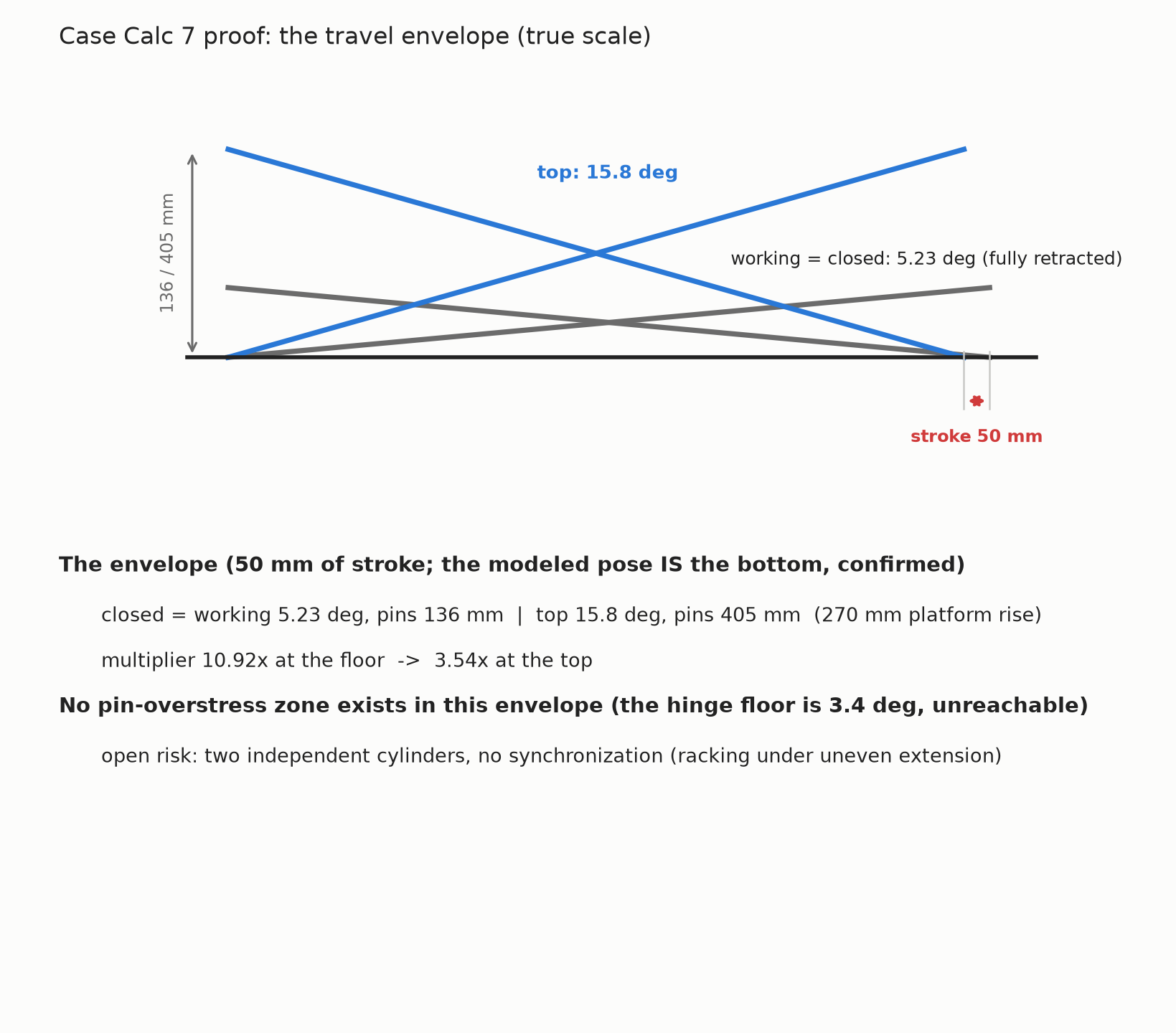
The travel envelope at true scale; the modeled pose is the bottom of stroke.
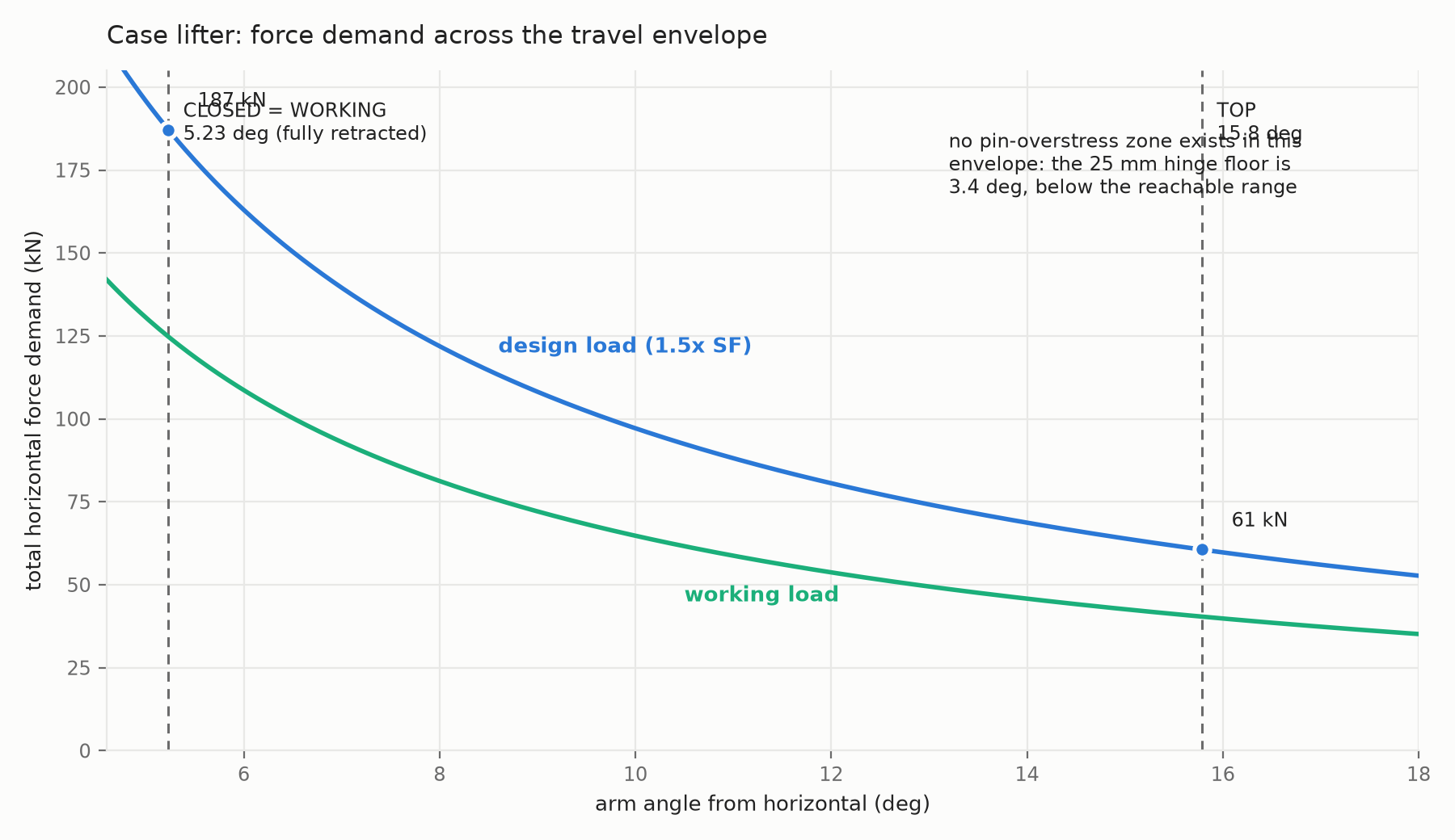
Force demand across the envelope, for the actuation vendor.
Recommendations
- Add cylinder synchronization: a flow divider, a rephasing circuit, or a mechanical tie between sides. Racking loads the lagging hinge beyond its half share and twists the arms, which are the tightest member on the machine.
- Treat the arm as the governing member: 105 percent of yield at the holed section under design load, a realised safety factor of about 1.43. Confirm the centre pivot gives genuine out-of-plane restraint, since the buckling check passes only on that assumption.
- Verify the center pivot's double-shear construction next time the joint is opened; the 91 percent single-shear reading is the thinnest joint margin on the machine. Specify the bush material against a projected bearing pressure of 95 to 125 MPa while it is open.
- Confirm material certificates at build; all margins assume mild steel.
Assumptions and limitations
- Material grade is unconfirmed; all stresses assume mild steel at a yield of 250 MPa.
- The only safety factor is 1.5 on the working weight, applied to the load. The 145 MPa shear figure is the shear yield, not a further-reduced allowable.
- Static analysis only: no dynamic or impact factor, no fatigue, and no stress concentration at holes. Both sides are assumed to share load equally except where the unsynchronized cylinders are flagged.
- Deformation and rupture loads are isolated pin-shear values on assumed steel; other components govern well below them.
- The center pivot is checked as steel shear only. The bushing material's own bearing pressure limit was not evaluated (projected pressure roughly 95 to 125 MPa depending on bush width); flagged for follow-up with the bushing specification.
- The arm's weak-axis buckling check assumes the centre pivot provides genuine lateral restraint. Unbraced over its full length the member would sit below the Euler stress.
- The lifted mass is payload plus platform. Arm self-weight is excluded, worth roughly 3.5 percent on top of every force here, and the 164.4 kg platform figure is measured with no padding.
- Frictionless pins and rollers. Real friction adds an estimated 10 to 20 percent to breakaway force and is not included in any figure here.
- Lug edge distance and tear-out were not checked, because plate edge geometry was never captured. Welds were not assessed. The analysis is 2D throughout, so racking, twist and rail misalignment are outside the model.