Case Study
Shaft Lifter Study
A single-stage scissor lift checked joint by joint, with the risks it hides at low angle.
The in-depth structural analysis of the shaft lifter: force multiplication, the joint reaction map, and every load-path check against a 1000 kg target, with an honest punch list of what stays open.
Scope
A single-stage scissor: two X-frames, pinned ends on one side (top and bottom), sliding ends on the other, driven by one horizontal cylinder at the base. The task was to check whether the structure can carry 1000 kg (plus a roughly 150 kg platform, safety factor 1.5 on working weight) across its real travel, and what must be corrected for it to do so. Actuation sizing was excluded: actuation-side components, including the cylinder cross member, are the actuation vendor's scope and were not analyzed. The force demand is stated where the vendor needs it. Material grade was unconfirmed, so mild steel is assumed (yield 250 MPa, shear yield 145 MPa).
Force required to lift
The horizontal actuator force is the lifted weight divided by the tangent of the arm angle. At the 9.82 degree working pose the multiplier is 5.78x, so the 16.92 kN design load demands 97.7 kN of horizontal push (65.2 kN at working load). The multiplier collapses as the lift rises, so everything dangerous happens in the first few degrees, and every structural load below inherits this number.
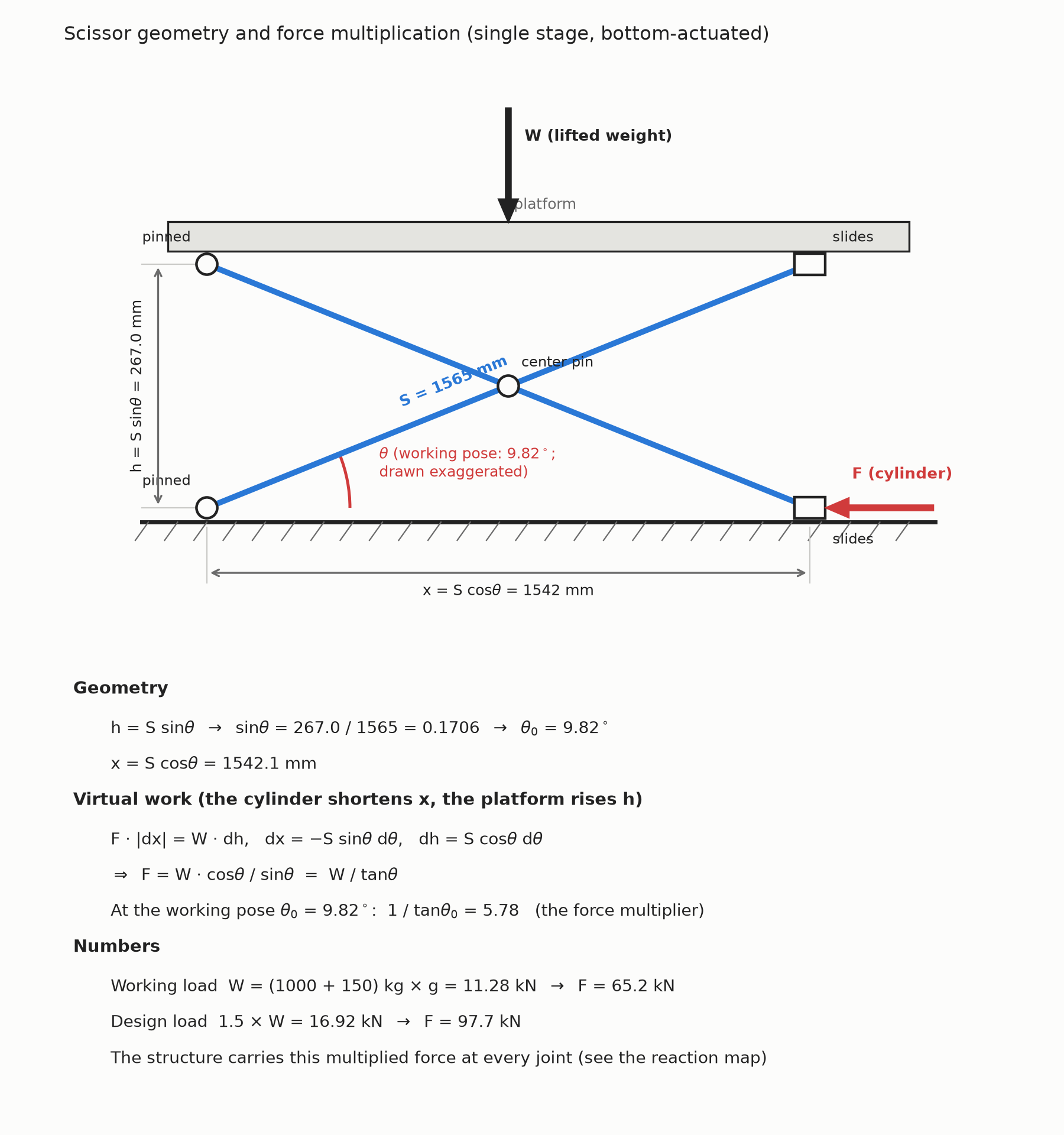
Geometry and the virtual-work derivation of the force multiplier at the true 9.82 degree pose.
The joint reaction map
A 2D free-body model per side converts the actuation force into loads on every joint. As built, with the load centered and all drive at the bottom, each side sees end hinges at 49.1 kN resultant, the center pin at 48.9 kN, and slider verticals at 4.2 kN. The center pin carries the difference between top and bottom actuation, which a bottom-only drive maximizes. Every structural check below consumes these reactions.
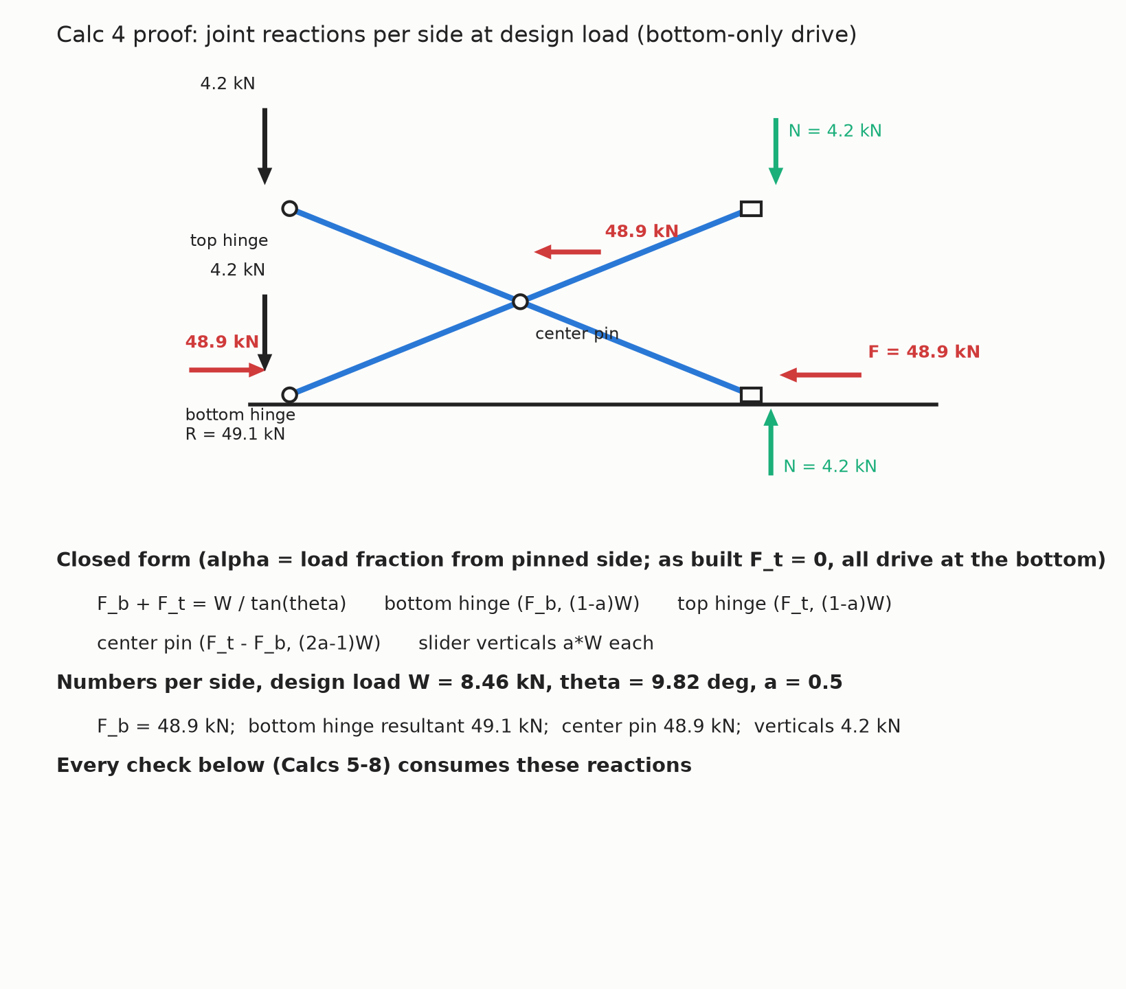
Reactions per side at design load, the input to every joint check.
Structural checks
| Check | Result | Verdict |
|---|---|---|
| Arm-end hinge axles (18 mm, double shear confirmed) | 96 MPa shear (67%); bearing 170 MPa arm plate, 72 MPa block | Stresses pass; unbuildable as documented (see below) |
| Center pins (24 mm, double shear) | 54 MPa (37%) | Pass, the one fully specified joint |
| Sliding-end linear bearings (2 per end) | 2.12 kN per block, 106 to 132% of static rating at design load, and 154% if the fitted carriage is LM25 class | Fail at design load, marginal at working load |
| Descent stop | Top face 457 mm down against 170 mm of reachable descent, misses by 287 mm | Non-functional |
Pin shear
The arm-end stack is block, arm plate, roller, arm plate, block, so the pin sits in double shear. The 18 mm block holes govern the pin diameter. At 49.1 kN the shear is 96 MPa, 67 percent of allowable, and both bearing checks pass. The 24 mm center pin runs 54 MPa. On the breakage envelope, the end pins deform permanently at roughly 2.4 tonnes of payload at the working pose and rupture between about 4.1 and 5.8 tonnes.
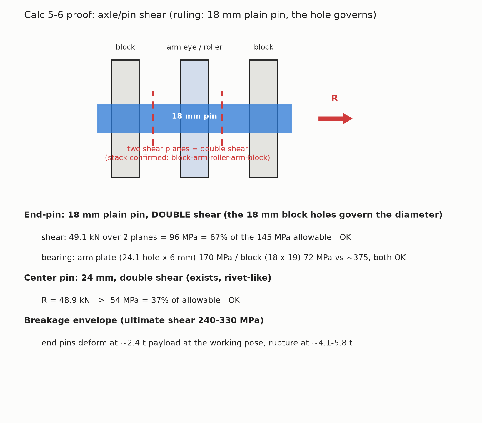
Shear planes and stresses under the confirmed double-shear construction.
Sliding-end bearings: the first failure
The actuated ends carry their vertical share through two linear bearing blocks per end. Each block takes 2.12 kN at design load against a static rating of roughly 1.6 to 2.0 kN, so 106 to 132 percent of rating. This is the machine's first structural failure under full load, independent of angle. A third block per end, or a higher-rated carriage, brings design load back to 71 to 88 percent. The failure mode is brinelling, which presents as sticky travel long before collapse.
One caveat on the rating itself: 1.6 to 2.0 kN is a class assumption, not a fitted part number. LM25-class bushings are catalogued nearer 1.37 kN, which would put the blocks at 154 percent of rating at design load and 103 percent at working load, turning the marginal working-load pass into a marginal failure. Confirm the carriage part number before sizing the fix. The verdict deepens either way; it does not change.
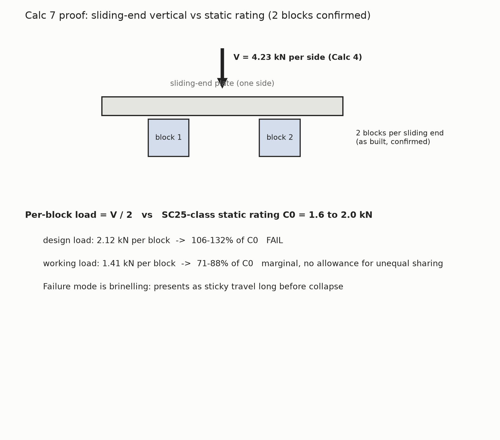
Per-block load against the static rating at the confirmed two-block count.
The travel envelope is the risk map
The modeled 9.82 degree pose is the working position, not the bottom. The piston can retract 19.92 mm below it to a true closed position of 3.56 degrees, where the multiplier is 16.1x, and extend 100.08 mm above it. Because every joint load scales with one over the tangent, lowering a load toward the piston's hard stop drives the pins toward their overstress floors: 6.5 degrees at design load, 4.4 at working load. The reachable bottom sits inside that zone.
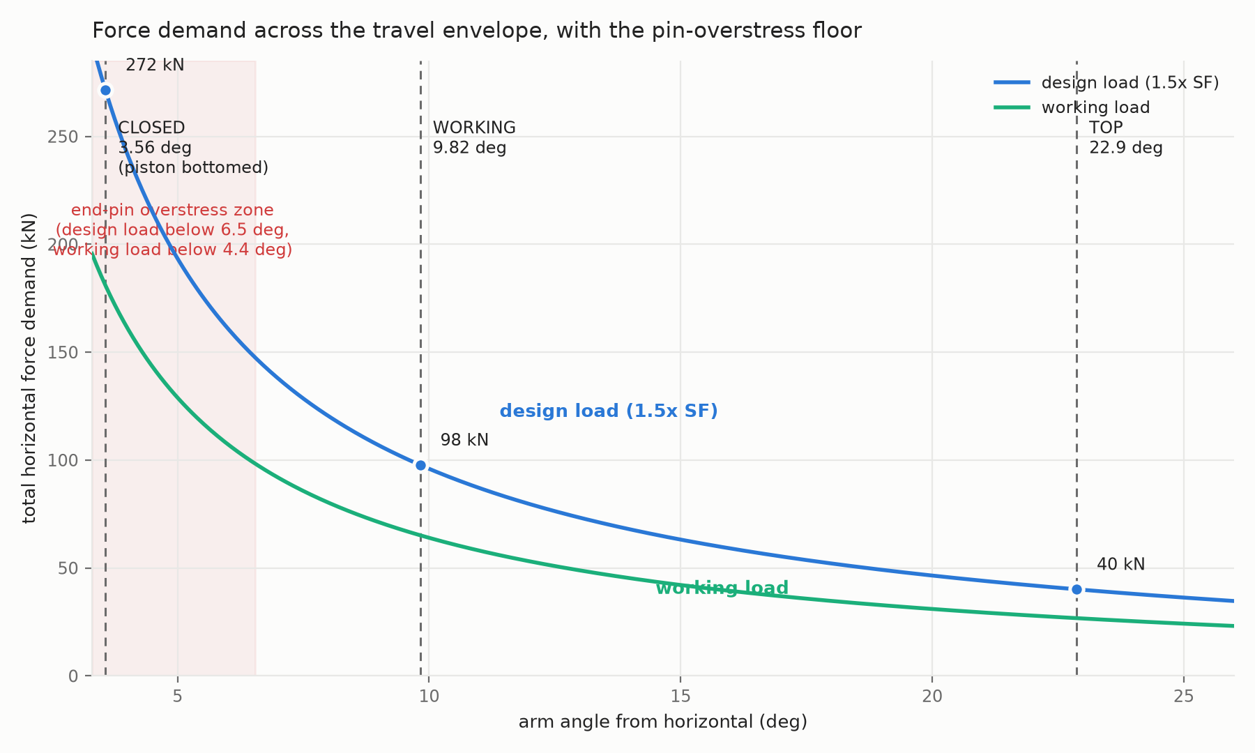
Force demand versus angle, with the pin-overstress zone shaded.
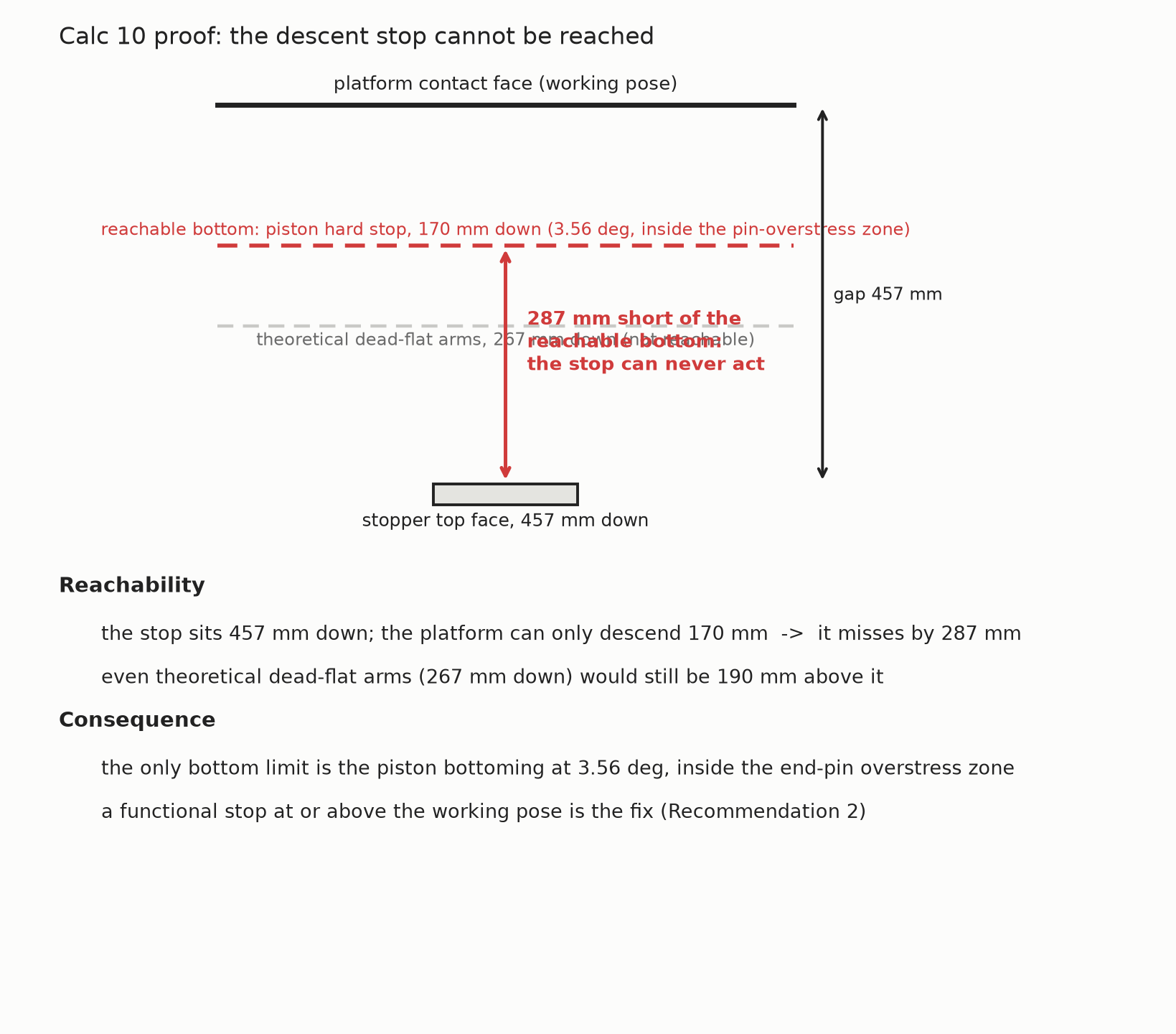
The descent stop cannot reach the platform, so nothing mechanical limits low-angle descent.
Loaded to 1000 kg from the reachable bottom, the outcome is permanent pin deformation rather than rupture. An empty platform can be parked at closed without harm.
Capacity, stated honestly
Capacity is pin-governed. From the lowest reachable point (3.56 degrees, 16.1x) the rated payload is 474 kg at the 1.5 safety factor, or 786 kg loaded to the shear allowable with no safety factor. The center pins and bearings do not govern from that point. The 1000 kg rating therefore exists only at or above the working pose, and remains contingent on closing the open items below.
The arm section: an open input, not a model failure
The arms are two flat bars per arm, each 6 mm thick. The depth at the crossing, the tall side-view dimension, has never been measured, and it is the last unknown on the primary load path.
An earlier reading of this page treated the bending model itself as suspect, on the grounds that a 25 mm depth returns roughly ten times yield while the machine demonstrably stands. An independent re-derivation settles that: the bending model is right, and the 25 mm figure is what cannot be. A 24.1 mm hole through a 25 mm deep plate leaves 0.9 mm of material, so 25 mm is a thickness or some other dimension, not the depth at the crossing. Nor are these arms two-force members. Solving the free body gives a genuine bending moment at the crossing of 3.26 kN.m per side, driven by the large horizontal drive force acting through the half-height offset between the pin and the crossing, and it peaks exactly at the pin hole.
The arm is a beam-column: that 3.26 kN.m acts together with 48.9 kN of axial compression at the same holed section. Including both, a 2 by 6 mm plate pair needs roughly 100 mm of depth to stay inside yield at design load, against the 82 mm the bending-only figure suggested. A 60 to 80 mm depth is consistent with a machine that stands and field-tested at 600 kg, and 60 to 80 mm would not clear 1000 kg at a 1.5 safety factor. The depth is unknown, the threshold is known, and the capacity claim for this machine is contingent on that one number.
Open items (punch list)
- Measure the arm plate depth at the crossing and run the beam-column check. It needs roughly 100 mm in 2 by 6 mm plates to clear design load with axial included. The capacity claim is contingent on this one number.
- Confirm the sliding-end carriage part number and its true static rating; an LM25-class carriage would move the bearing verdict from 106 to 132 percent up to 154 percent.
- The arm-end axle is a stepped or sleeved custom pin that was never drawn, specified, or retained, so the hinge is unbuildable as documented even though its stresses pass. Fit and positively retain a proper axle.
- The primary-load-path fasteners (hinge hold-downs, cylinder bracket) are unmodeled, yet roughly 49 kN per hinge must pass through them. Specify them.
- Confirm material certificates; every stress here assumes mild steel.
Recommendations
- Fit a third linear bearing block per sliding end, or higher-rated carriages. This removes the one outright structural failure at design load.
- Install a functional descent stop that engages at or above the working pose, so a loaded platform can never be driven into the low-angle overstress zone. This is a prerequisite for any actuation upgrade.
- Specify and positively retain the arm-end axles, stepped or sleeved to match the stepped bores.
- Close the arm beam-column check with the measured section and final drawings.
- Confirm material certificates before build.
Assumptions and limitations
- Material grade is unconfirmed; all stresses assume mild steel at a yield of 250 MPa.
- The only safety factor is 1.5 on the working weight, applied to the load. The 145 MPa shear figure is the shear yield, not a further-reduced allowable.
- Static analysis only: no dynamic or impact factor, no fatigue, and no stress concentration at holes.
- Deformation and rupture loads are isolated pin-shear values on assumed steel; other components govern well below them.
- Actuation-side components, including the cylinder cross member, are the actuation vendor's scope and were not analyzed.