Project
Water Opacity Sensor (WOS)
PIC-based optical sensor PCB for water clarity classification via light intensity.
Designed and fabricated a PIC-based optical sensor PCB that measures water opacity via light intensity, classifies safe and unsafe ranges, and supports remote start/stop and digital interfacing.
Why
This subsystem was built to classify water clarity using a low-cost optical method. The goal was to convert light intensity through a sample into a stable electrical signal, then output an unambiguous safe/unsafe state that could be shared with the broader team system.
Constraints
- Readable, stable output despite sensor variance and ambient light noise.
- Simple safe/unsafe classification with adjustable thresholding.
- Integration with a team-controlled master system via digital I/O.
- Designed, built, and validated within a class project timeline.
What
The system uses a photoresistor to sense light attenuation, conditions that signal with an op-amp stage, then uses a PIC microcontroller ADC to classify opacity and drive digital outputs (status LEDs and I/O lines).
Key capabilities
- Measures opacity via light intensity and converts it into an ADC-readable signal.
- Outputs safe/unsafe states based on a programmable threshold range.
- Supports remote start/stop and digital interfacing with the programming lead’s subsystem.
Block Diagram
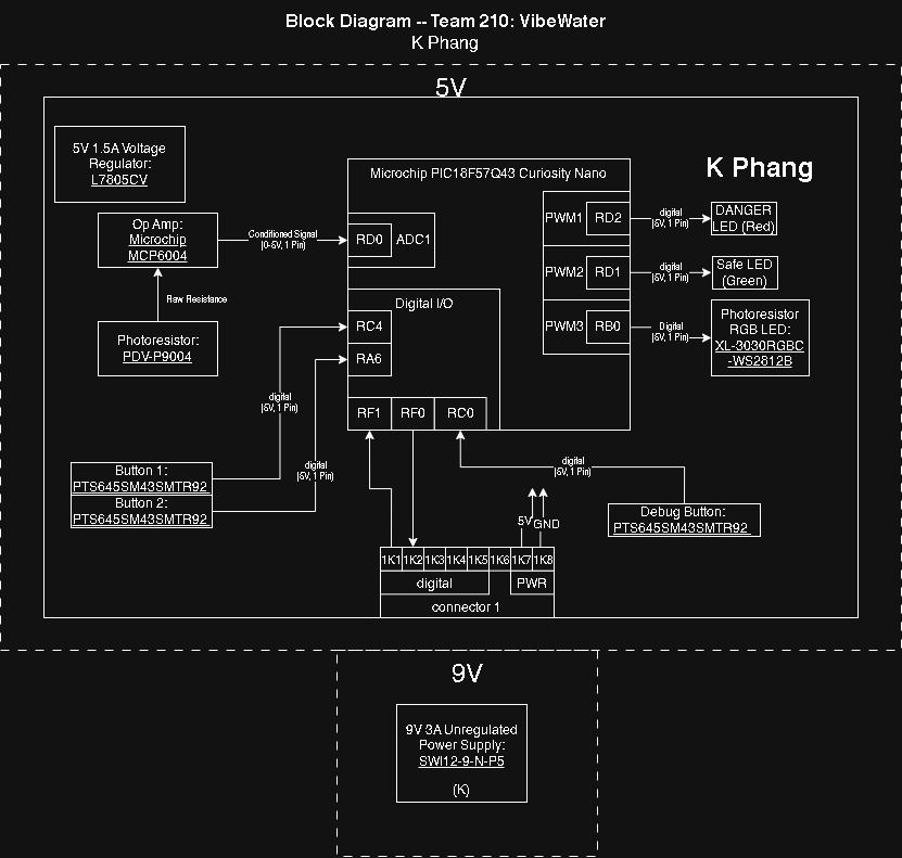
Signal flow from sensor to conditioned analog output to PIC ADC and digital state outputs.
Schematic
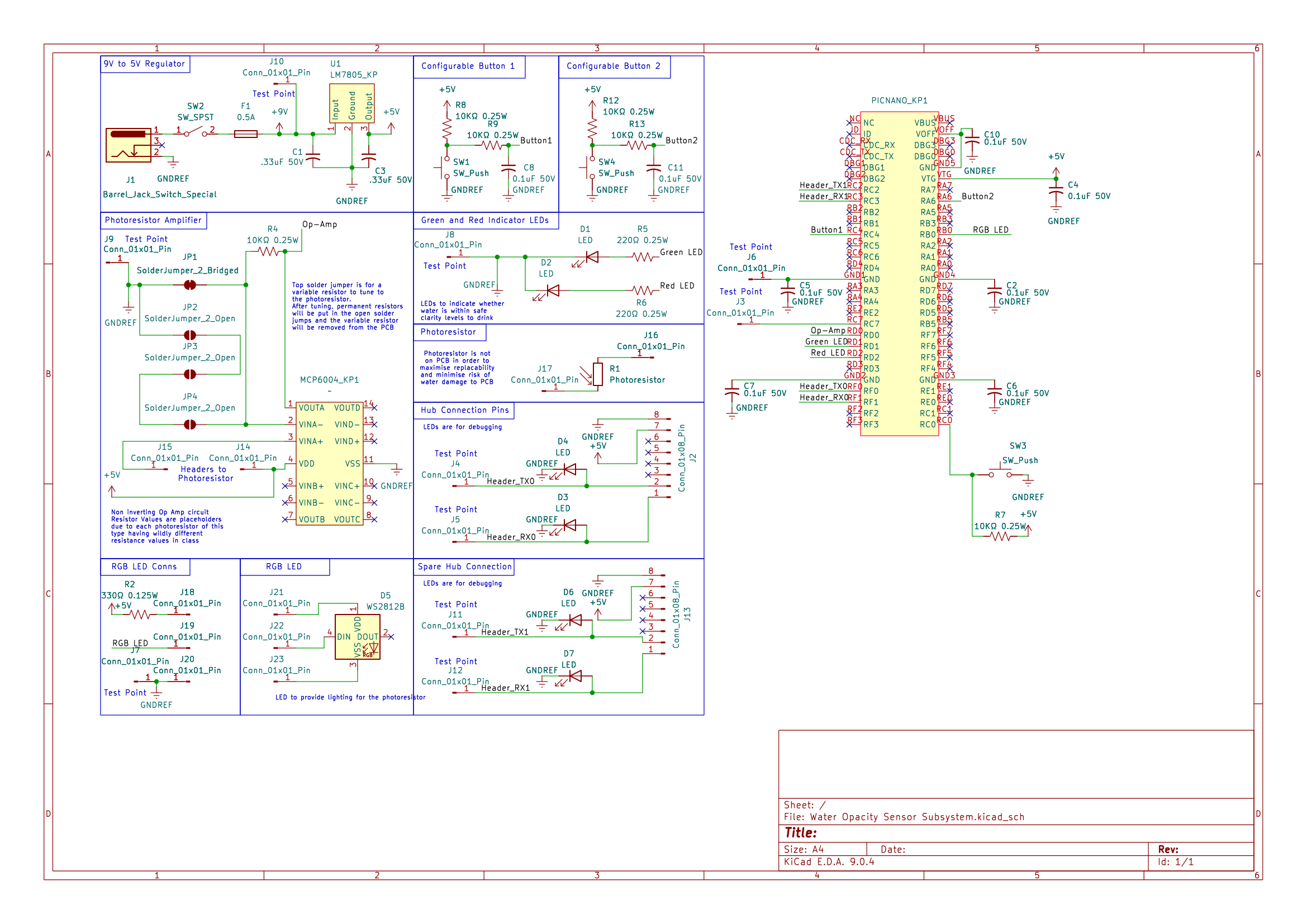
Includes photoresistor amplifier path, LED indicators, and PIC Curiosity Nano pin mapping.
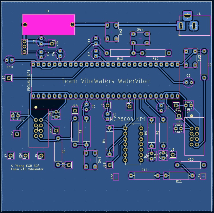
PCB Layout
Front
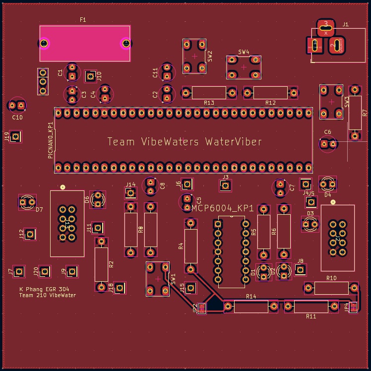
Back
How
I owned the full sensor subsystem from schematic through validation. I designed the analog signal conditioning and PCB in KiCad, assembled and debugged the board, and implemented the ADC high/low interpretation to generate stable digital states. I coordinated the digital interfacing details with the programming lead to ensure clean board-to-board communication.
Build process
- Defined sensing approach, selected photoresistor and op-amp signal conditioning strategy.
- Captured schematic and PCB layout in KiCad with test points and integration headers.
- Assembled board, verified power and analog signal path, then validated ADC behavior.
- Mapped safe/unsafe thresholds to digital outputs and confirmed I/O compatibility with the team system.
Testing & Results
The sensor successfully classified opacity based on light intensity and produced a stable safe/unsafe output. Threshold behavior was configurable in software, and the subsystem supported remote start/stop plus digital state reporting.
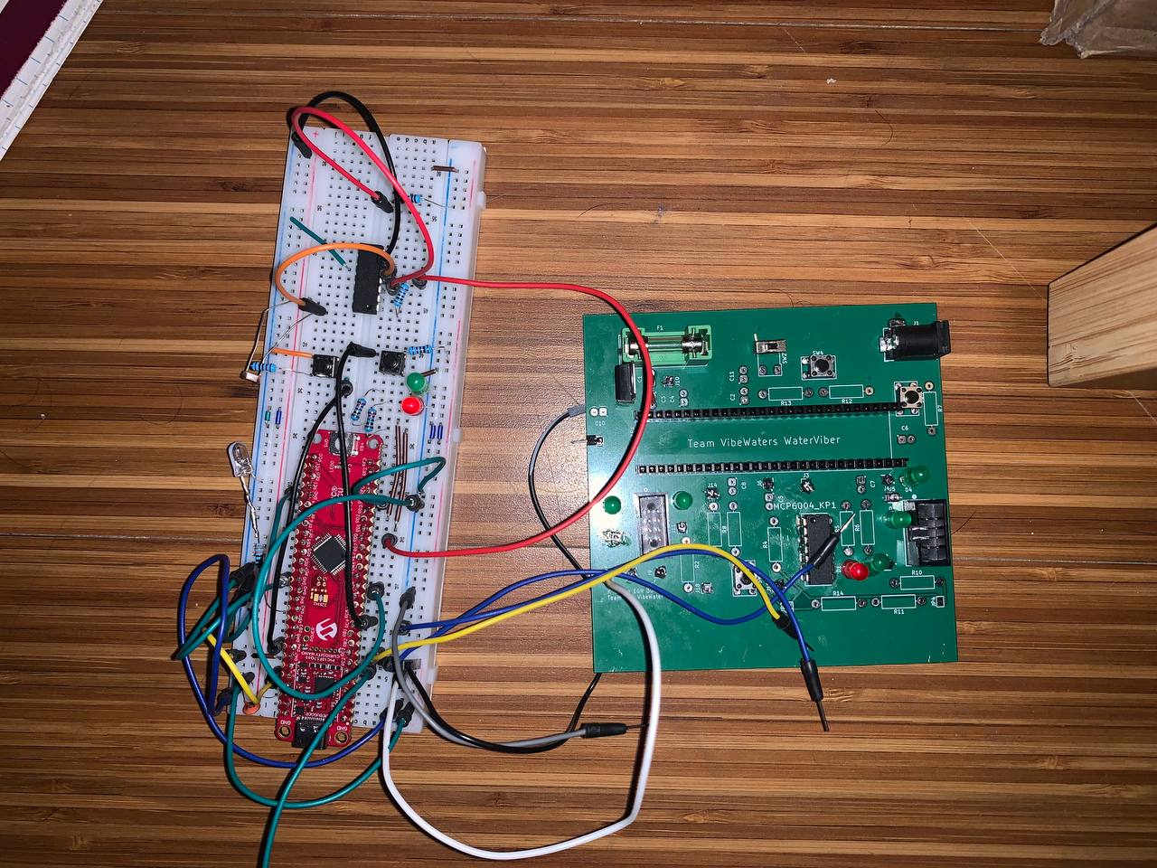
Assembled system and integration setup.
- Validated analog conditioning and ADC read stability across varying light conditions.
- Confirmed safe/unsafe state transitions at the programmed threshold range.
- Verified digital I/O outputs for downstream integration and status indication.
What I'd Do Next
- Add mechanical light shielding to reduce ambient sensitivity and improve repeatability.
- Calibrate against known turbidity standards to map readings to real units.
- Replace photoresistor with a photodiode for faster response and improved linearity.